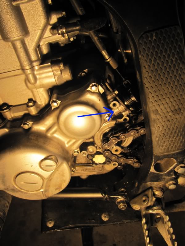
Problem: Oil is leaking out of here.
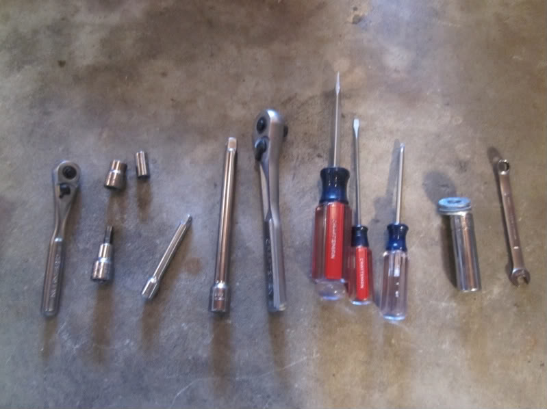
Tools needed:
5mm hex key
8mm socket
10mm socket
8mm wrench
1/2” socket and a couple washers
Flat head screwdrivers of varying sizes
Torque Wrench
Oil Seal - Yamaha Part Number 93102-12004-00
Clutch Cover Gasket - YP# 3D7-15453-00-00
Optional: Small Philips Head, Magnetic Pickup
Start on the right hand side of the bike. (There is no need to drain the oil.)
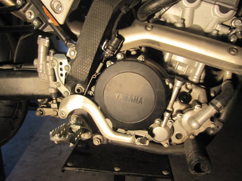
Remove the rear brake: Disconnect attached springs, remove safety pin on rear of pivot, and use 5mm hex to loosen the pivot.
Remove plastic clutch cover: 3 8mm bolts. Longest goes in the lower right. Torque rating: 10 Nm (7.2 ft•lb)
Remove metallic clutch cover: 6 8mm bolts. The 4 long bolts go in the upper hemisphere. Torque rating: 10 Nm (7.2 ft•lb) There are also two alignment dowels, so be careful not to loose them.
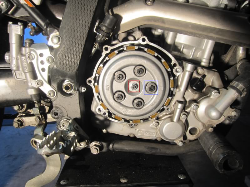
Remove Clutch Spring Bolts: 5 10mm bolts. (Blue square) Torque rating: 8 Nm (5.8 ft • lb) in a criss-cross pattern.
Remove the pressure plate: Pull straight out. A light push on the left-hand clutch lever will make it easier.
Optional –
Remove clutch plates: Just pull them straight out. When installing them start with a fiber, followed by a metal.
Adjust clutch disengagement: (Red box) Applicable if you have run out of adjustment at the lever. After reinstalling the Spring Bolts, loosen the locknut. Turns in the clockwise direction of the Phillips head will disengage. Clockwise, engage.
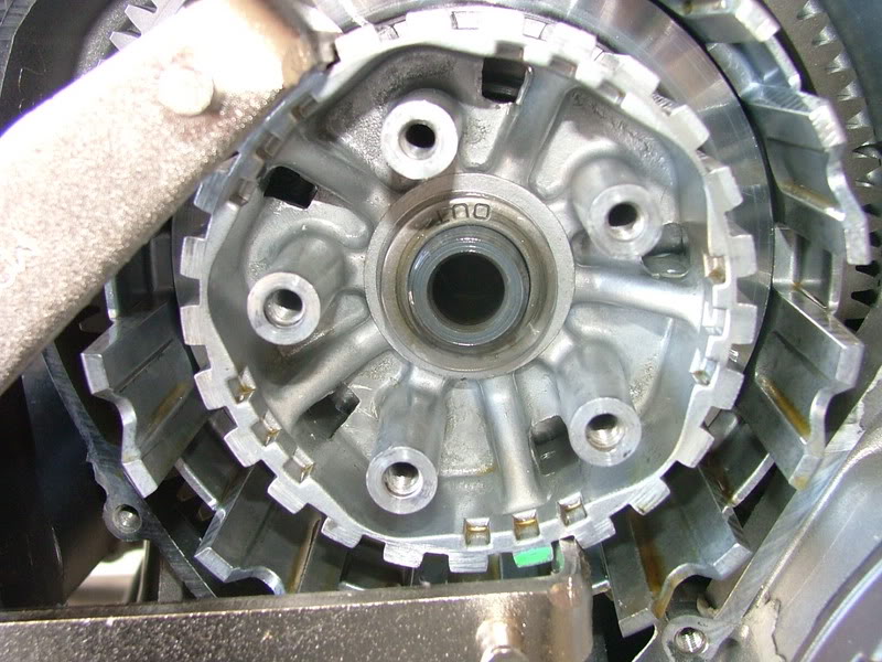
(Forgot to take pictures of the clutch, so this is off a different bike.)
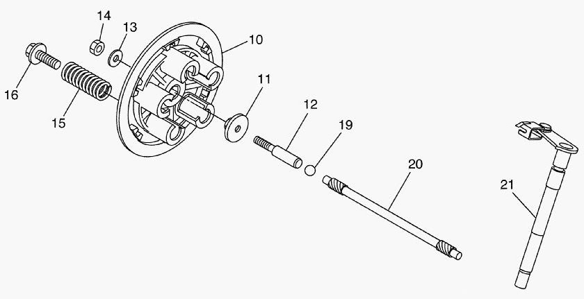
The clutch whack: Part 20 rests in a groove in part 21 (which is why we couldn’t just pull it out.) Temporarily reinstall the pressure plate with plunger to push parts 19 and 20 to operating position. Remove the pressure plate. Go to the left-hand clutch lever and do one fast forceful squeeze of the lever. There is no way to know if you did it right until later, so you can repeat until you “think” you’ve got it right.
This step allows you to skip removing the clutch basket as instructed in the service manual.
The ball bearing: Though the service manual tells you that it will come out after the basket, it will happy fall out of the big hole in the middle as you work on the other side… Either remove it with a magnet or be prepared and vigilant for it to evacuate on its own.
The Other SideRemoving the countershaft sprocket cover and sprocket will gain you some additional room.
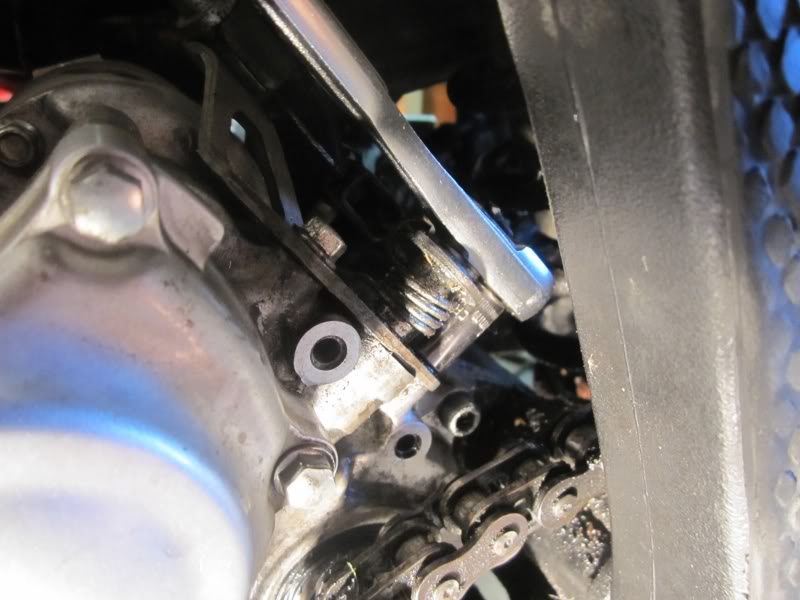
Remove the lower bolt: 8mm bolt. 10 Nm (7.2 ft•lb)
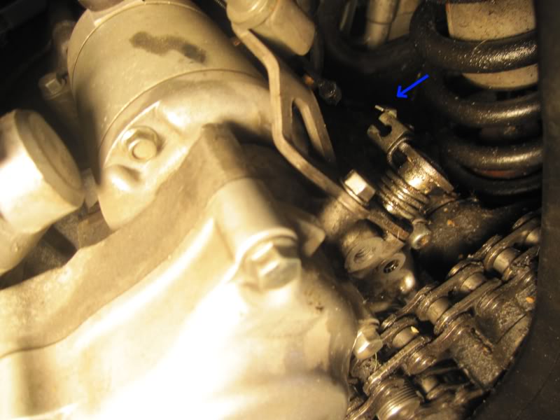
Remove clutch cable: Pry the lock tab up and then slide the cable out.
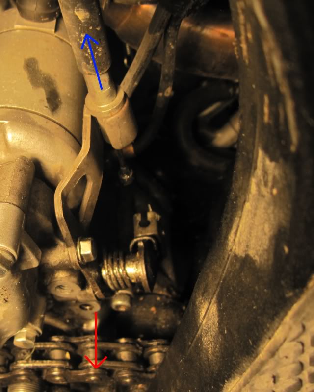
Remove the bracket: Pull the cable up through the upper mount. Remove the upper 8mm bolt. Pull the bracket straight towards yourself, supporting the activator.
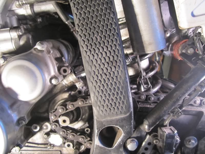
Remove the activator: If you did the “clutch whack” correctly, it will slide easily out. There is room between the frame and shock, so it’s nice and easy.
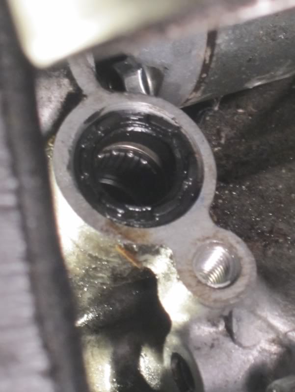
Remove the offending seal: If only it were that easy…
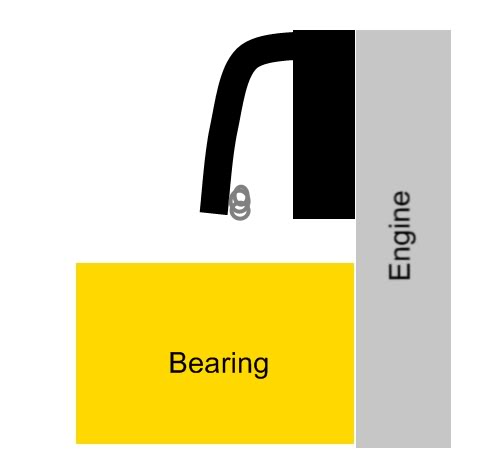
Here is a cross section of the situation. The thick rectangle is a hard plastic, the droopy part is soft plastic and the silver circle is a spring.
I was eventually able to pry it out using a screwdriver and numerous angles of attack. You have to be very careful not to damage the bore of the cylinder and not to drop anything down in there. Slide the screwdriver in the gap between the seal and bearing and push up. Work your way around the seal. (If anyone has a better idea, I am all ears.)
Installing the seal: Your thumb can only push that hard plastic in so far and the there isn’t much room for other strategies. Luckily the bike comes with its own seal driver. Head over to your earlier removed parts and grab 2 of the long bolts from the metallic clutch cover. Install them through the activator bracket and screw them in a few turns. Match a socket diameter to the seal diameter (1/2 inch worked for me, but all tools vary wall thickness) and shim with washers to install in the “driver”. There will be limited clearance, so you’ll use the 8mm wrench to tighten each side evenly down. Check often to see that the seal is in the proper place.
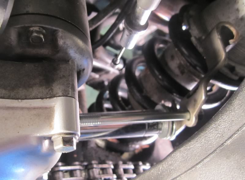
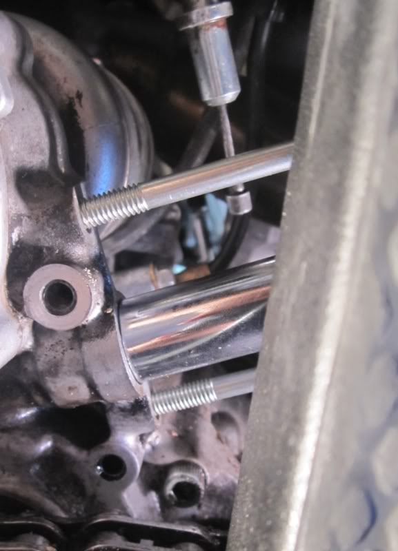
Oil seal replacement complete! In the manner of step-by-steps before me, installation is the reverse of removal.
General observations:
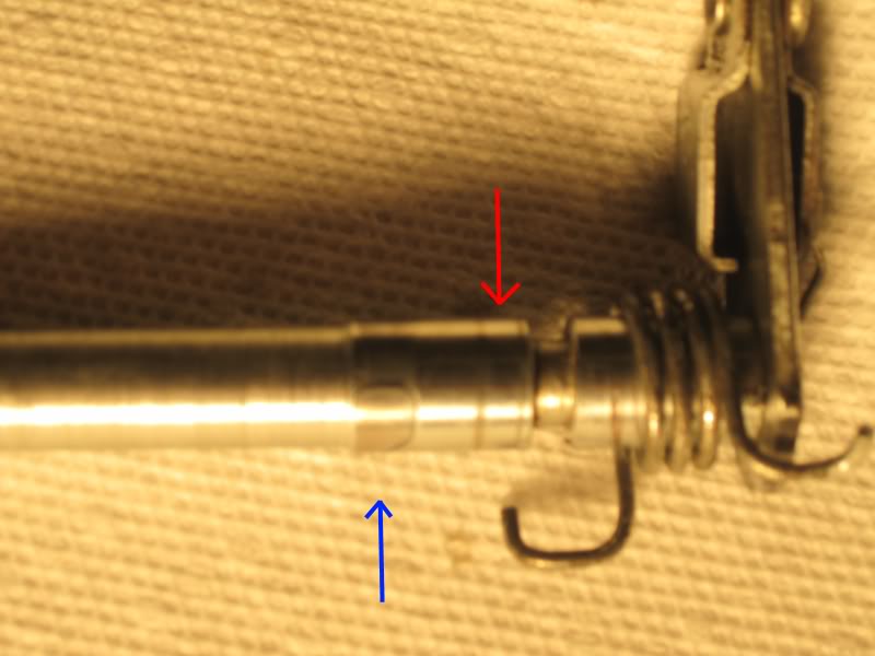
This is what my activator rod looks like after 10k miles. The blue arrow points to the wear caused by the bearing that is only on one side. The red arrow is a buildup of either seal material (same color) or debris, possibly the cause of the leak. For reference in this picture the spring is on backwards.
Questions, clarifications, improvements? Let me know.
